
Glue the two base halves together with a layer of paper between them (I
just use newspaper). Once the glue dries, mount the blank on the lathe using a faceplate/ring with screws
arranged so they won't interfere with the finished ring.
|
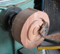
True the bottom
face and cut the groove that the wire will lay in - I was lucky the groove
ended up the right size to match my stepped bowl jaws for when the piece is
reversed.
|
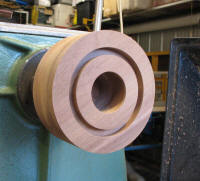
Trim the outside to size and cut the hole for the centre radius almost
right through the blank.
|

Reverse the piece on the chuck and shape the top as close to round as you
can get it.
|

Drill the centres of your posts out. I needed to use a 10mm bit which
won't fit through my live centre on the lathe so I resorted to the pictured
method, drilling in from each end, I was only a mil' or two out of alignment
in the finish which was fine. The 'V' block guide is shimmed up so the drill
aligns with the blanks centre height, everything is clamped in place and
away you go.
|

The posts are then mounted between centres on the lathe and rounded down
to the chosen diameter. The closer to the 'bend' you go, the less work there
is later on.
|

The top of each post was 'cupped' to allow the seat of the light fitting
to drop right in...
|

...plus a bit more to allow space for an earth lug. The brass cup will
be attached by screws through the cup into the post.
|

The drill press table makes a good height-adjustable platform to use in conjunction with the belt sander
to remove the waste from the posts and round them over.
|

Split the base ring along the glue-join and clean/true the ends up. I
decided to dowel the joins in the base to help with positioning more than
adding strength.
|

Glue up the two outside joins only at this stage so the two sides can be
separated to allow easy access for blending the posts and rings together and
to allow the clock-block to be fitted in the final glue-up.
|

The concave side of the wave shape of the clock-block was formed by
passing the block across the table-saw at an angle, sneaking the blade up in
steps of just 1 or 2mm at a time....
|
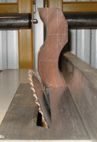
... and taking the excess off the convex side as pictured.
|

The wave was refined with a mixture of hand-planing and hand powered
curved sanding blocks.
|

A simple rig for holding the clock-block perfectly square while drilling
the hole through from the bottom for the threaded inserts.
|

I mounted the inserts on a length of 6mm rod to screw them into place to
make sure they were aligned properly.
|

Mark and drill the posts and clock-block to take the dowels that will
join them. I also stepped each hole 1 or 2mm deep with a 10mm bit so the
brass tube that would slip over the dowels would appear to be inside the
timber. Glue up the middle of the base and the clock-block at the same time
and clamp - yes, it is tricky!
|
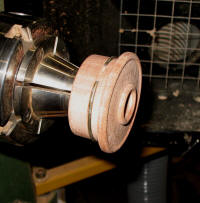
Turn the plug any way you like as long as it is removable to access the
clock for battery changes. Because the wood was still moving, I turned the
plug a loose fit and cut a groove to hold a piece of springy wire as a
retainer - worked a treat! Alternatively, if you don't cut a recess for the
clock, it could be pulled out from the front but I think it would look too
obtrusive.
|
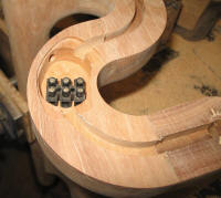
I used a trimmer (small router) to hollow a section of the base as a
junction box for the wiring. This was later covered with a piece of hard
plastic attached with a screw in each corner.
|

To get the type of light fittings I wanted, I had to buy a chandelier
and cut it up. This compromised the earthing of the fittings as they are not
double-insulated. My solution to this was to run and attach an earth as
pictured. If you want to use this type of fitting and are not a licensed
electrician, you MUST get one to do the wiring for you to ensure everyone's
safety.
|
|

|

|
 |
 |
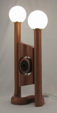
... and yes, it did win the competition which has a very tidy $400
prize attached.
The competition is open to anyone so see you in it next year
eh!
|
|